
In this article we consider ways of improving high quality output of Multi-Layer Ceramic Capacitors (MLCC) for use in PCB Manufacturing
What are Multi-Layer Capacitors?
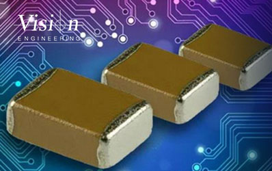 Multi-Layer Ceramic Capacitors (MLCC) are added to Printed Circuit Boards (PCBs) which are then used in home electronic devices, computers and a variety of products within the telecoms sector. This has created a huge global demand for low cost, high quality MLCC, creating pressure to improve current manufacturing and quality control processes.
An MLCC consists of printed internal electrodes which are then coated with a ceramic dielectric foil with high insulation properties. This is then subjected to a high temperature sintering process which forms a micro-chip. Up to three layers of metal are then deposited onto the two ends of the MLCC to create external electrodes. The MLCC is then attached to the PCB.
This complex manufacturing method means that the likelihood of defects is high and the process can be both lengthy and costly. The drive towards the miniaturisation of components and the subsequent denser packing of PCBs has increased the complexity of the process even further.
In order to remain competitive many manufacturers have introduced Surface Mount Technology (SMT) into the production process further increasing the risk of imperfections producing an end product that is unfit for purpose.
Clearly, the need for quality control throughout the manufacturing process is of paramount importance, as the cost of delivering defective components to a manufacturing client has a negative impact on both reputation and the bottom line.
 Quality Control in the Manufacturing Process
There are various stages of the manufacturing process where quality checks need to be conducted in order to deliver a high quality end product. Each of these visual inspections require magnification in order to accurately assess such miniature parts.
Early checks in the manufacturing process revolve around the quality of the MLCC itself. Hundreds of MLCC components are placed on a tray under a microscope. This tray is subjected to a gentle vibration allowing slight movement of the parts making it easier to spot any colour differences which signal imperfections.
Initially the operator will be checking for exposed electrodes and any deformation to the shape of the part. The next stage would be to scrutinise the surface for any inconsistencies or cracks in the porcelain coating. This is important as an imperfect coating would reduce the insulation properties causing an electrical short when voltage is applied to the PCB.
Any defective components are then removed using tweezers, before allowing the tray with the approved MLCC parts to move to the next stage of the manufacturing process.
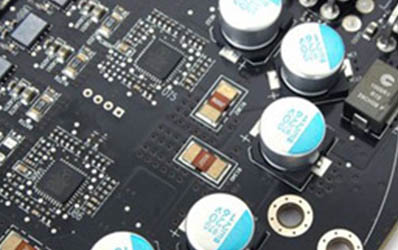
Using the SMT manufacturing process the MLCC components are then mounted directly onto the printed surface of the PCB, leading to the next stage of quality inspection. In this phase MLCC is checked once more for any damage that may have occurred during the attachment phase. The integrity of the MLCC attachment to the PCB is also checked. Like the earlier quality check, this stage of inspection requires magnification due to the minute scale of the components. If the part is deemed to be faulty, re-working will need to be conducted under the microscope. Re-working needs the operator to melt the solder and remove the MLCC together with any residual solder before printing solder paste directly onto the PCB and placing a new MLCC onto the board.
All of these checks are critical to ensuring that a good quality product is delivered. However the large volume of parts that need to be checked under a microscope does cause problems.
Improving the Inspection Process
The discomfort of working with a traditional microscope means inspectors are unable to work for long periods of time without losing concentration. Whilst a limited depth of field places further demands on concentration levels as minor imperfections are more difficult to spot. When it comes to re-working, poor hand-eye coordination slows the pace of re-working. In order to improve production efficiency and ensure optimal quality checks these issues need to be satisfactorily resolved.
It was with these problems in mind that the Lynx EVO was developed. The eyepiece-less viewer means operators have greater flexibility when it comes to head movement. This enables users to work for extended periods without losing concentration or suffering from neck or back pain. As operators need to take fewer breaks the production process becomes more efficient.
The large depth of field offered by the Lynx EVO offers a more detailed view of the component making slight defects more obvious, improving the accuracy and speed of surface checks. Additionally the long working distance of up to 176mm means that hand-eye coordination is greatly improved, making working with tweezers and soldering equipment far easier and more accurate. Finally, the Lynx EVO has a range of stand options, offering adaptability within the changing inspection environments of the manufacturing process.
To find out more about how the Lynx EVO can improve your quality processes contact us.
